
I learned a few noteworthy things today, but it’s my bedtime, and I’m only writing about one of them under the topic of Networking.
Manchester Encoding
I learned all of this from the brilliant Ben Eater at this YouTube video. Watch that rather than read this. Nevertheless:
In order for two computers to communicate with each other, they need to agree on timing. This can pose a problem.
A common way of communicating information is by fluctuating a voltage up and down. Almost everything can be expressed in binary. Underneath the layers of abstraction, the words you are reading right now are 1s and 0s. This is kind of wild if you’re honest, but even the least computer-savvy understand (or at least accept) this is true. Therefore, all you need to communicate any information are 1s and 0s. So for networking, you just need some way to represent this. We call these representation symbols. (I say “we” like I was consulted, but I was not. I was told these are called symbols, and now I am calling them symbols.) Take the following image:
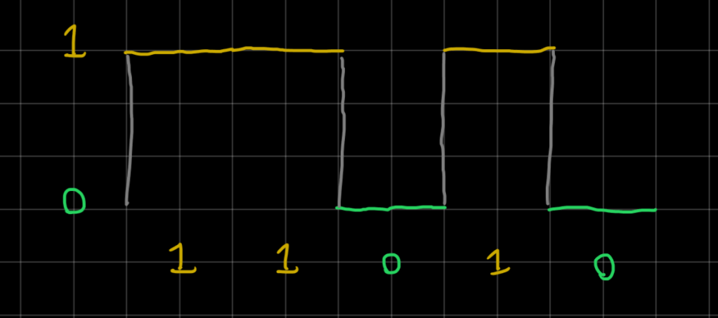
We take the high point to represent “1” and the low point to represent “0”. This could be 5 Volts and 0 Volts or it could be 1 Volt and -1 Volt, or whatever else. The important thing is that the two points are distinguishable.
You can pretty easily see how this message comes across, and clearly it reads 11010. (Really really it would read 01011, because we send the first bit first, so the other computer catches the information from right to left.)
But this wouldn’t be clear if I didn’t write the numbers. Take image #2:

Now we have a very different message (1111001100). In this image, one space on the grid corresponds to each 1 and 0. Each of these grid marks would represent some space in time, and we have to define how long each symbol will last. There are a few ways of doing this, but in some cases, even that is not enough. Even if both the sender and receiver agree on a time interval (clock speed), you could have a situation where the clocks are out of sync. Even small differences and fluctuations can blow your entire signal to nonsense.
Enter Manchester Encoding. The IEEE 10Bass-T apparently uses this. But the idea is: instead of saying “high = 1” and “low =0”, we can define the change from “Low to High” as 1 and “High to Low” as 0. The clock speed can be interpreted directly from the signal if this type of code is agreed upon. Take this image for example:
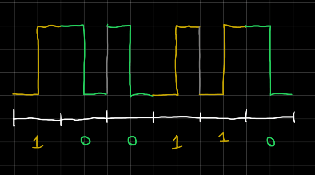
Even if I didn’t write the tick marks, you would be able to read the speed based on the signal. The only transitions that occur, occur on two time intervals: 1 grid or 2 grids. 2 grids has to be the clock speed, because it is the only speed that can lead to a sensible signal. I was confused by this at first, because it looks like the gray lines of transition could be confused as symbols since they are also transitions. So why can’t the clock speed of this signal be 1? If the gray lines were actually signals, the transitions between 1 and 0 would make no sense. They are neither 1 nor 0, since they are not changing state. Test if that makes sense by reading the binary signal and clock speed (grid spacing per signal) of a drawing with no markers or hints. If you know the signal uses Manchester encoding so that “Low to High” = 1 and “High to Low” = 0, then there is only one answer.

Synchronizing clock speed presents a problem. With a simple but clever rule, this problem is solved. No expensive components or hardware. No new physics or discoveries. No magic. Just a little bit of applied logic can pin down the possible interpretations of a phenomenon from infinite to just one. A little bit of logic creates meaning.
That might be a little poetic for such a nerdy topic, but I don’t think I’m far off.
That’s what I learned today.
The blue signal is 11011011 at a clock speed of 1 grid FYI. (read right to left). If I didn’t make that make sense, watch Ben Eater’s video at the top and get the good stuff from the source.
